
Product Code :Product Name :Stock : |
11103MultiLevel Inverter (5 Level) Available
|

|
Option-1 : Buy this Product as it is
Option-2 : Buy this Product With Your Identity / Name / Brand
Option-3 : Customize the features of this Product as per your Need

Make Changes in the board, add or remove the features that you want. Customize this board as per your need and send us the specifications so that we can process the board and deliver them exactly as per your requirement.
Boards Will be designed with your brand name. No Manufacturer Identity. Minimum Order Quantity = 10 |
|
Product Information
Hardware Requirements:
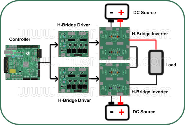
The following hardware’s are required in order to realize cascaded single phase 5 level 50Hz AC inverter.
1. Constant DC source – Two numbers,
2. H-Bridge MOSFET inverter modules – Two numbers,
3. Controller Section (uC or FPGA),
4. Isolated MOSFET Gate Driver - Two numbers,
5. Load.
Working Principle:
Note: For proper understanding of the isolated MOSFET driver section. Kindly go through single phase H-Bridge inverter document.
AC voltage at the output of a cascaded h-bridge is realized by adding voltages in steps from the input DC. To identify the switching sequence for each voltage level at the output, proper path to the load should be found by turning on combination of switches.
To get both positive and negative voltage step levels at the output. In the case of a load resistor, it should be considered that if the current flows from pin 1 of the load resistor to pin2 as positive voltage levels and for negative voltage levels current should flow from pin2 to pin1 of the load resistor.

