Product Code :Product Name :Stock : |
11101Single Phase Inverter Available
|

|
Option-1 : Buy this product as it is
Option-2 : Buy this Product With Your Identity / Name / Brand
Option-3 : Customize the features of this Product as per your Need
Make Changes in the board, add or remove the features that you want. Customize this board as per your need and send us the specifications so that we can process the board and deliver them exactly as per your requirement.
Boards Will be designed with your brand name. No Manufacturer Identity. Minimum Order Quantity = 10 |
|
Product Information

Hardware Requirements:
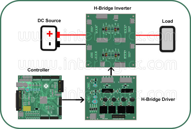
The following hardware’s are required in order to realize a single phase 50Hz AC inverter.
1. Constant DC source,
2. H-bridge MOSFET Inverter module,
3. Controller Section (uC or FPGA),
4. Isolated MOSFET Gate Driver,
5. Load.
Working Principle:
1. The principle idea that is required to drive an inverter and to produce a 50Hz AC signal at the output, is to understand the time based switching sequence required to fire the MOSFETs in H-Bridge formation.
2. A PWM signal generated at desired frequency such as 2, 5 or 10 KHz (as shown in the below figure) is mixed with the pulse envelope generated to fire the subsequent MOSFETs to produce 50Hz ac signal across the output load.
3. The above said principles are implemented in a controller (uC or an FPGA) by writing a program (C or VHDL) and burning it into the device. Upon powering on the controller firing pulses are produced at the controller IOs. The firing pulses are then isolated using an “Isolated MOSFET gate driver”. Pulses produced at the output of isolated MOSFET gate driver are then fed into the respective MOSFET’s gate pins.
4. MOSFET triggering pulses produced by the controller would either be off 3.3V (CMOS) or 5V (TTL) logic. The purpose of isolated MOSFET gate driver is to translate that input voltage level to 12V level and to protect controller from high voltages by providing isolation.
5. To produce 50Hz AC Voltage across the load using a constant DC sources. For basic inverter operation, PWM with fixed frequency and duty cycle should be generated. The PWM produced inside the controller should be mixed with the envelope pulse produced for each MOSFET onboard the H-Bridge configuration.
6. For continuous inverter operation, the below shown switching sequence should be repeated every 20ms.